Week 1: Introduction & Documentation
Circuitry & Arduino
This week we were tasked with completing a simple circuit on a breadboard to illuminate an LED lightbulb. I quickly learned the importance of resistors in tempering the amount of current that arrives at the load after burning through my first bulb. But, things looked up on my second go-round as I shifted the finicky wires into submission and the circuit worked! Pictured below is the final product.
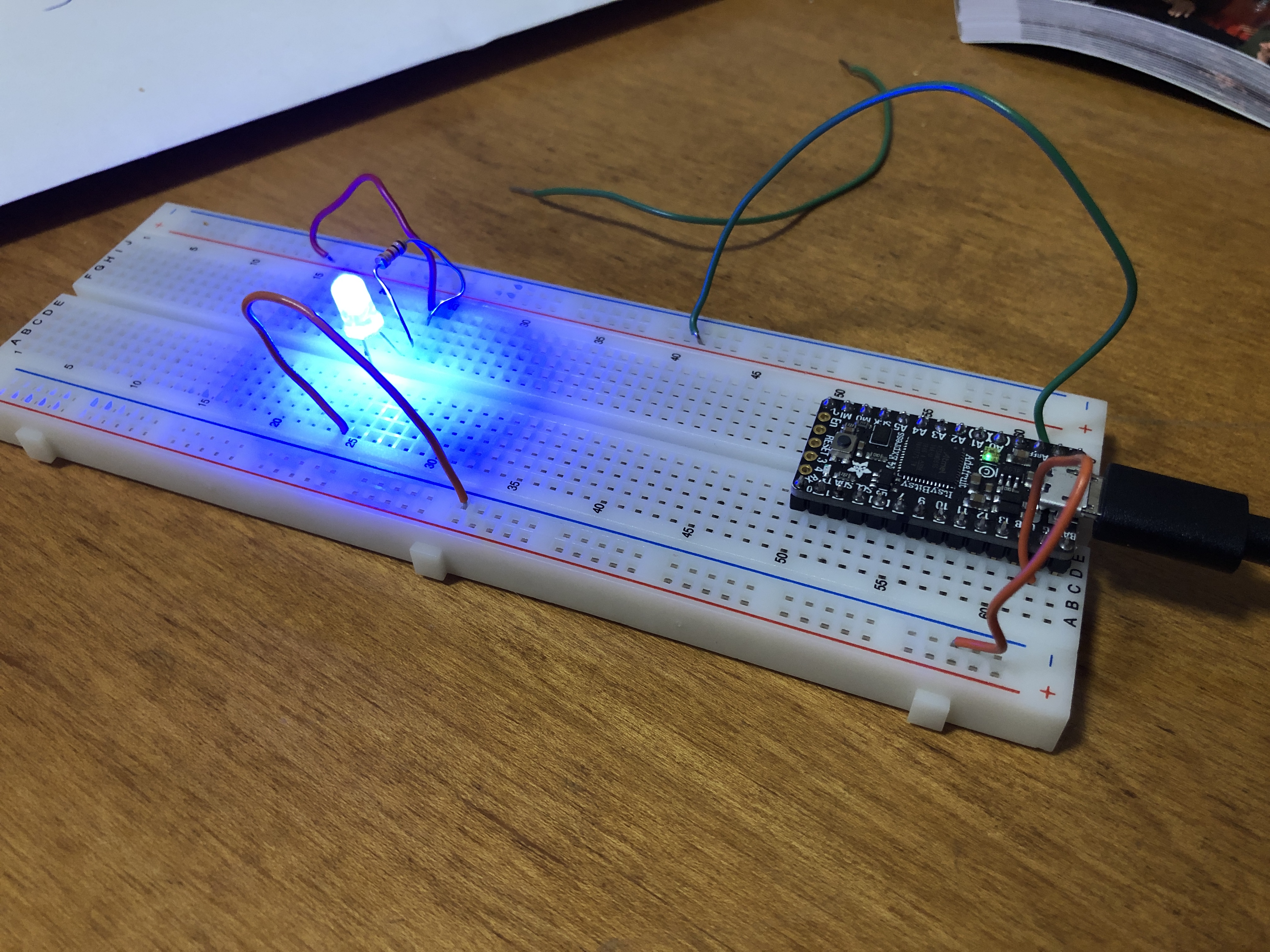
After grappling with the breadboard, I moved onto Arduino, connecting the microcontroller to my computer's USB port. From there, I installed the appropriate boards and used the source code for a 'Blink' loop. I then compiled the code and let 'er rip! The red LED on the microcontroller blinked successfully, and I could speed up or slow down the lapse of time in between the pulses. Below is a video:
Working with the circuits presented a great opportunity to re-aquaint myself with electricity and its properties following an ~eight-year hiatus. This project helped me to better understand how solitary electrons are ousted from the outer valence shells of conductive metals and passed from one atom to another to create the constant flow that characterizes current. Also, it was intriguing to learn how the resistor's value can be calculated with Ohm's law (and demonstrated with colorful banding) to ensure that the LED is kept under its maximum current rating and avoid blow-outs such as that I initially instigated. The multimeter showed the dissipation of approximately 0.5V across the resistor.